3. Beginning: GUI
3.1. Introduction
This usecase presents a few of the more important ParaView GUI features. A full list of features can be found in the ParaView Guide.
Data can be opened by going to File → Open. Example data files can be found in the Examples directory, located in the upper left of the Open dialog.
3.2. Customize Settings
paraview allows users to customize settings. The most important ones are
found in Edit → Settings → General. These are:
Auto Apply - Also found as an icon below the Macros menu.
Auto Convert Properties - Automatically call Cell to Point, Point to Cell, or extract components from vectors as needed.
Transfer Function Reset Mode - when to update the minimum and maximum for the Color Legend.
Grow and update on Apply - default. This means only update when told to.
Grow and update every timestep. This means to update the Minimum and/or Maximum only if the current timestep exceeds these numbers. Basically, Add and grow.
Clamp and update every timestep. Set the minimum and maximum every timestep, from the data this timestep. This is not recommended behavior, since it makes comparing frame to frame confusing.
Scalar Bar Mode - just leave this one alone.
Default timestep -
Go to first timestep - default.
Go to last timestep

3.3. Information tab
Open can.ex2.
Press Apply.
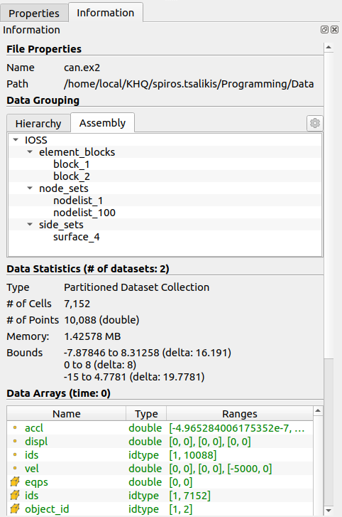
Open the Information tab.
The first section is the File Properties of the dataset.
The second section is Data Grouping, which tells you what blocks and sets you have in this dataset.
The third section is Data Statistics which tells you:
The number of cells
The number of points
The amount of memory used
The bounds which give the X, Y and Z bounds of the bounding box.
The fourth section is Data Arrays which gives information on each variable, including the min and max. Note that this is for the current timestep only.
The last section is Time which gives a list of all timesteps, with their associated time.

3.4. Right click menu based commands
Open can.ex2.
Apply.
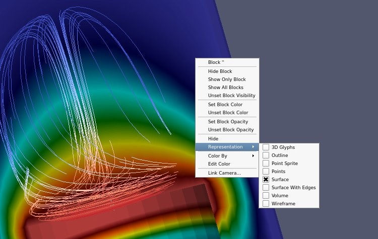
Right click on the object.
Block Name
Block specific visibility commands
Block specific coloring and opacity
Representation and coloring commands
Link Camera
3.5. Split windows
Open can.ex2.
Apply.
Drag the can around with the left mouse button until you can see the can.
Split screen vertical – i.e., one above the other. This is the little box with the horizontal line.
Select 3D View.
Turn the eyeball on for can, in the Pipeline Browser.
Split screen vertical – i.e., one above the other. This is the little box with the horizontal line.
Select 3D View.
Turn the eyeball on for can, in the Pipeline Browser.
Did you know?
You can always Undo using  icon or Redo using
  icon.
icon.
This last command was a mistake. Lets undo it. Undo, Undo.
We undid one too many commands. Lets redo it. Redo.
Select the bottom viewport.
Split screen horizontal – i.e., one next to the other. This is the little box with the vertical line.
Select 3D View.
Turn the eyeball on for can, in the Pipeline Browser.
Now lets link the cameras.
Right click on the upper window.
Click on Link Camera.
Click on the lower right window.
Do the same between the two bottom windows.
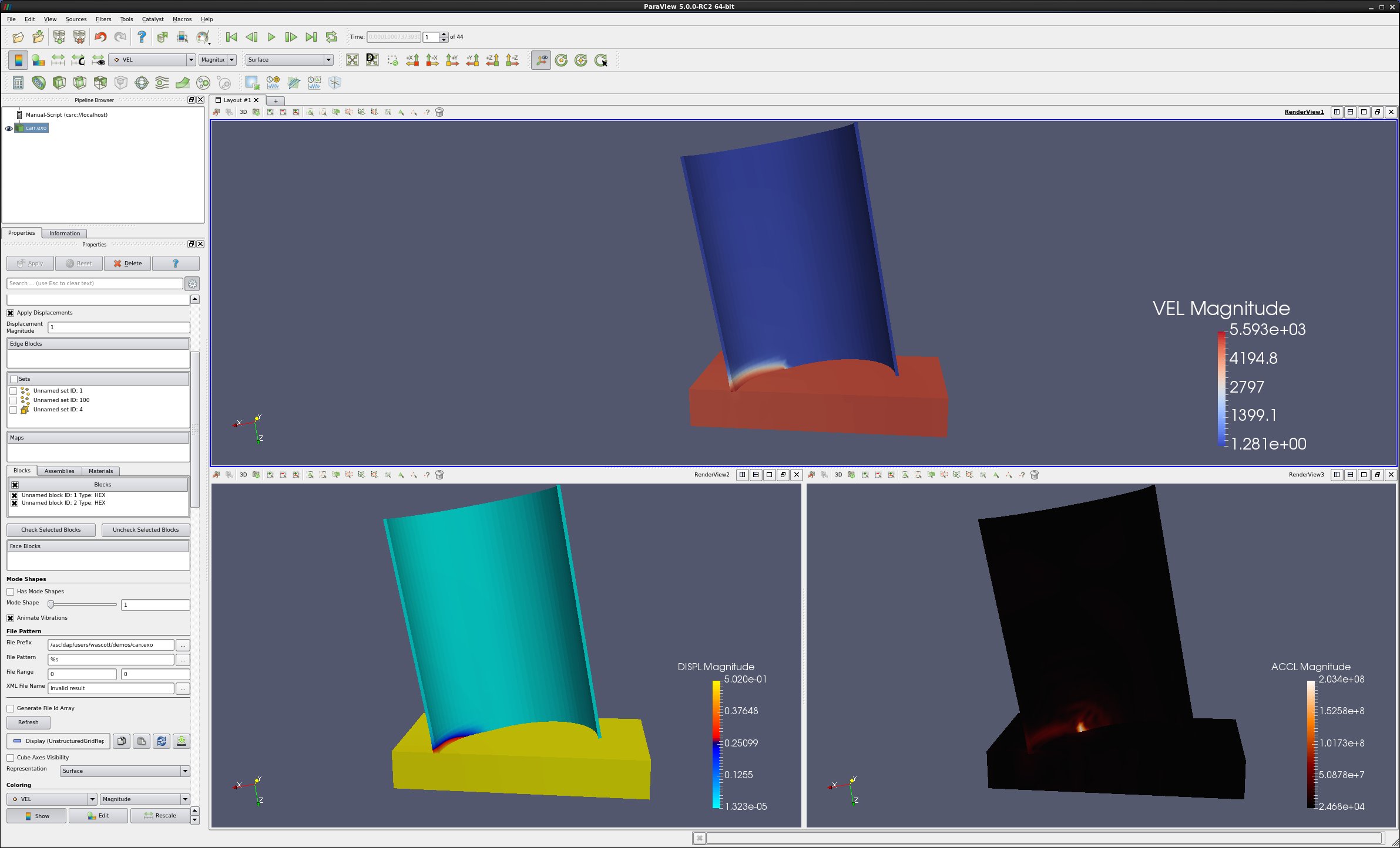
Click in the lower left window, set Coloring to DISPL.
Turn on Color Legend Visibility.
Click in the lower right window, set Coloring to ACCL.
Turn on Color Legend Visibility.
Click in the upper window, set Coloring to VEL.
Turn on Color Legend Visibility.
Go to the last frame.
Click on Rescale to Data Range.
Go to the first frame.
Play.
3.6. Move/control windows
Select the top window.
Click on the Maximize button of the upper window.
Click the Restore button of the upper window.
Next, Using the left mouse button, grab the title bar of the lower left window and drag/drop it into the upper window. These two windows have now switched places.
Finally, grab the divider between the two lower windows and drag it left and right. You can also move the divider between the upper and lower windows.
3.7. Unlink windows
To unlink the windows, we use the Link Manager. Tools → Manage Links.
Select the second link.
Click Remove.
Close.
Now, grab and rotate can in the three windows.
Finally, delete the bottom two windows, using the Close button.
3.8. Control the center
Click on the Show Center
 icon. Notice that this toggles the center cross.
Click on the Pick Center
 icon, then select a location on the can.
Rotate the can, and notice where it is rotating.
Click on the Reset Center
 icon, returning the rotation location
and center cross to the center of the object.
icon, returning the rotation location
and center cross to the center of the object.
3.9. Auto apply
ParaView now has the ability to auto apply commands. This button looks like this  and is to
the left of the blue question mark.
and is to
the left of the blue question mark.
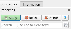
3.10. Properties tab
The Properties tab has three buttons on top: 1) Apply button, 2) the Reset button and 3) the Delete button. The Reset button will undo any Properties tab changes that a user accidentally has made. Below these three buttons is a search feature. Search will find Properties tab items, irrespective of them being standard or advanced. An example would be Opacity.
3.11. Advanced Properties tab
The properties tab initially is in standard layout. To get to the
advance layout, click the gear icon. Advanced reader or filter properties
are found here. The advanced layout icon is  .
.
3.12. Copy/Paste/reset/Save parameters
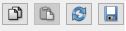
On each section of the Properties tab there are four icons, as follows:
Copy the state of that section of the Properties tab to the clipboard.
Paste the state from the clipboard to this section of the properties tab. This allows you to copy and paste state between filters.
Reset to factory defaults.
Save this state as the user default.
3.13. Move the camera
ParaView allows the user to change and store the position of the camera.
Such controls as Roll, Elevation and Azimuth are available.
The Adjust Camera  icon is on the left side of the row
of icons at the top left of the 3d window.
icon is on the left side of the row
of icons at the top left of the 3d window.
The Adjust Camera dialog box looks like this:
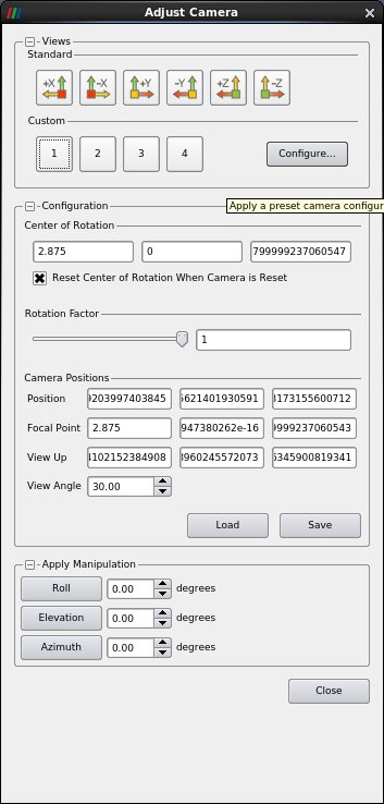
Useful controls that I often use (in order) are as follows:
Custom Configure - Save up to 4 camera positions.
Azimuth - rotate around the vertical axis. Be sure to hit the button after entering a number.
Elevation - rotate around the horizontal axis in the plane of the screen.
Roll - rotate around the axis coming out of the screen.
View angle - basically a zoom in.
Camera position - where the camera is.
Focal point - where the camera is looking.
You can always recenter the object using the Reset icon. First, however, be sure to change View angle back to 30.
3.14. Matplotlib characters
If needed, open can.ex2..
Select the DISPL variable.
Move forward one time step using the Next Frame icon.
We want to add an alpha character after DISPL.
Open the color editor.
Open the Edit Color Legend icon. It is the little color legend with the ‘e’ over it.
Modify the Title DISPL to say DISPL $\alpha$
Here is how to change a 2d plot of EQPS to EQPS (uV/m)
Plot Over Line. Apply. Turn off all variables other than EQPS.
Change the Legend Name from EQPS to EQPS ($\frac{muV}{m}$)
Matplotlib Mathtext formats are described here: https://matplotlib.org/2.0.2/users/mathtext.html
3.15. Axes Grid
Open dataset disk_out_ref.ex2.
In the Properties tab, scroll down and select Axis Grid.
Note that you can edit the Axis Grid attributes.

3.16. Lighting - Specular
It is possible to change the specular highlights in ParaView. This is on the Properties tab, about half way down. It is called Lighting: Specular. Note that reflections can look like the center of the color map, thus specular highlights are turned off by default.
3.17. Slice View and Layouts
Open disk_out_ref.ex2.
Apply.
Set Coloring to Temp.
Select Clip.
Turn off the Show Plane.
Apply.
ParaView supports numerous simultaneous layouts, or windows, into your data.
Select the X to the right of Layout #1 (upper left side of the 3d window).
ParaView also supports different views than 3d views. Here is how to show your data as a slice view.
Select Slice View
Turn visibility on for disk_out_ref.ex2.
Set Coloring to Temp.
Left click in the window, and drag disk_out_ref around.
Move the left, upper and right clip planes by dragging the black wedge.
You can intermix different view types.
Split horizontal.
Turn visibility on for disk_out_ref.
Paint by Temp.
You can also connect the cameras for the different views. This can be done through the Tools → Add Camera Links menu.

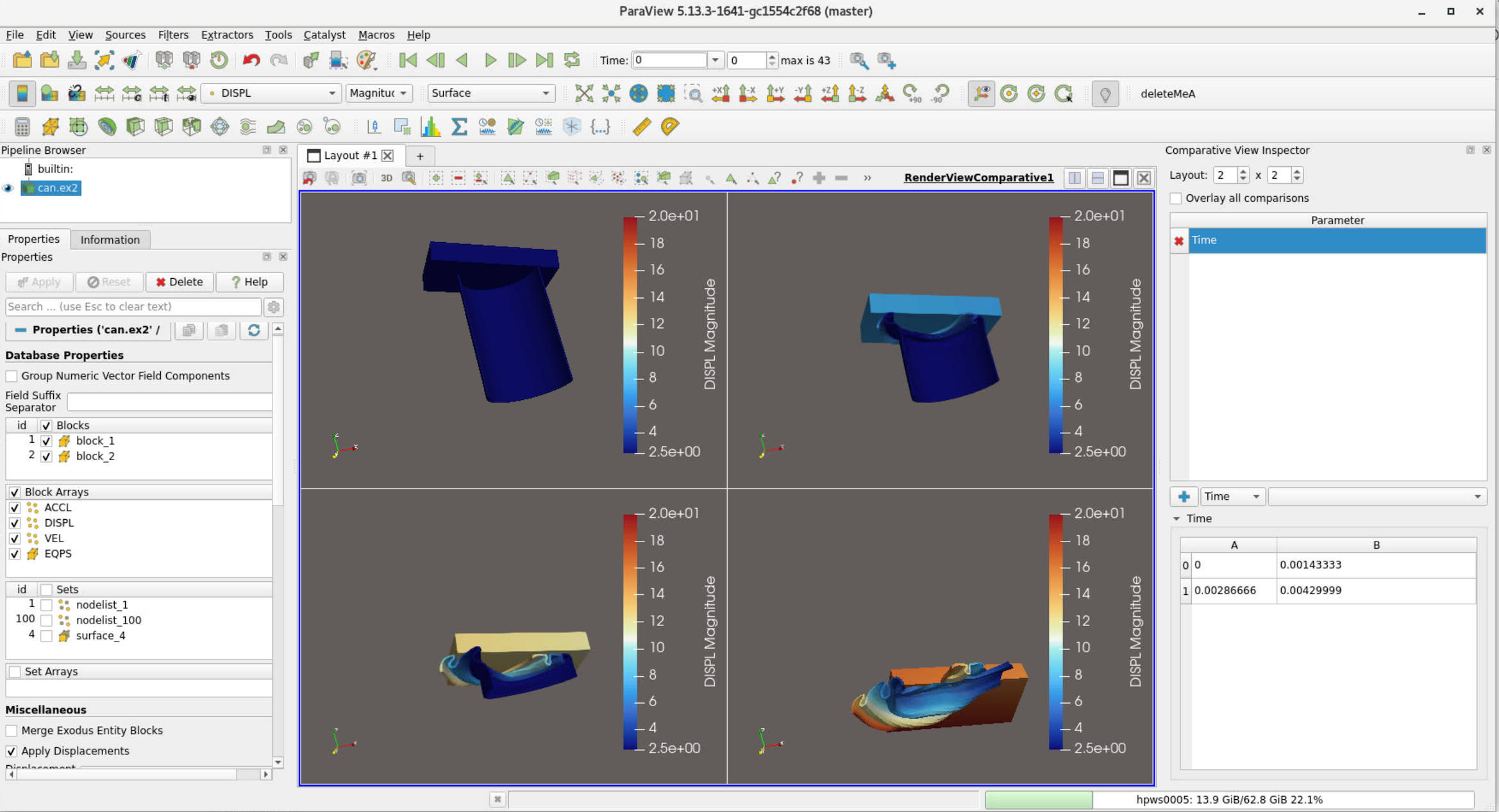
3.18. Render View (Comparison)
ParaView can compare different time steps at the same time. This is called Comparative View.
Open can.ex2.
Apply.
Split view horizontal.
Select Render View (Comparative).
Turn on visibility on the can.
View → Comparative View inspector.
Click on the blue +. This creates a 2X2 set of views of can.ex2 at four different timesteps.
3.19. Customize Shortcuts
You can create shortcuts to Menu items (such as Filters) in ParaView.
Tools → Customize Shortcuts.
Find Wavelet. If it has a shortcut already, click Clear.
Click in the Press Shortcut button.
Now, select a shortcut, such as CTRL W.
Close
Now, click CTRL W, and you have a Wavelet.
Apply.